Overview
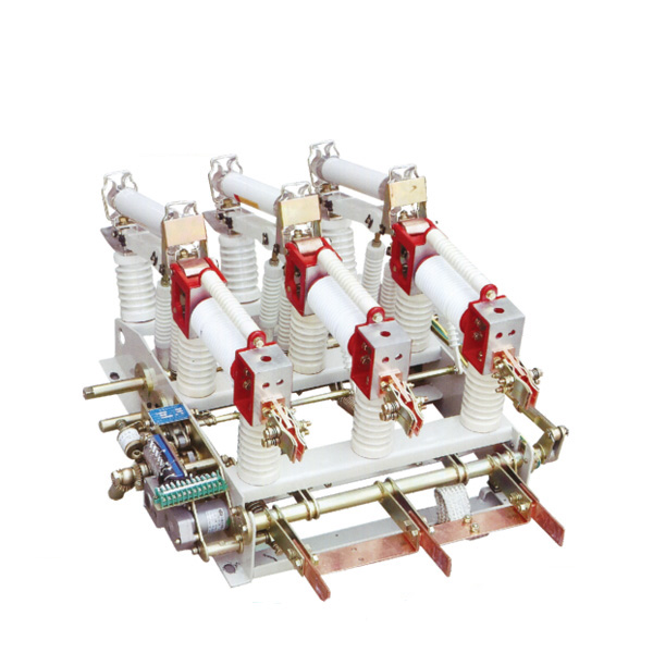
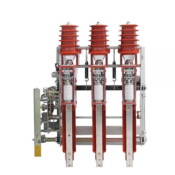
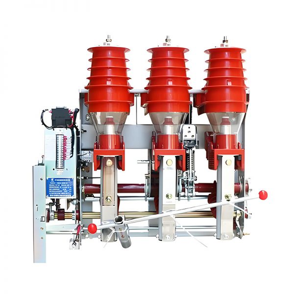
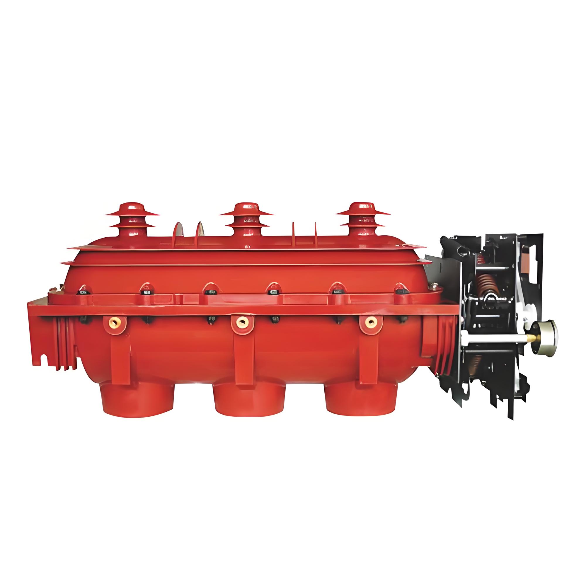
FL(R)N36-12D indoor high-voltage SF6 load switch is an indoor switchgear with a rated voltage of 12KV. It uses SF6 gas as the arc extinguishing and insulation medium, and has three stations: collector, isolation, and grounding. It has the characteristics of small size, easy installation and use, and strong environmental applicability.
The FL (R) N 36-1D indoor high-voltage SF6 load switch is equipped with an intelligent control unit and protection module, which realizes the functions of “three remote” and rear energy control. It can be used for the control and protection of electrical equipment in industrial and mining enterprises, civil power supply, and secondary substations. The combination of load switch and fuse can effectively control the spread of faults and provide synchronous three-phase power supply isolation within 20ms of breaking fault current, especially suitable for transformer protection and ring network power supply.
Operating Conditions
1. Altitude: ≤ 5000 meters
2. The environment temperature: upper limit +40℃, lower limit -40℃
3. Relative humidity: daily average value is not greater than 95%, monthly average is not greater than 90%;
4. The seismic intensity does not exceed 8 degrees;
5. There is no fire, explosion hazard, serious pollution, Places subject to chemical corrosion and severe vibration.
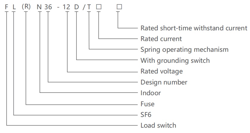
Model and meaning
Technical Data
| Item | Unit | Parameter | ||
| FLN36-12D | FLRN36-12D | |||
| Rated voltage | kV | 12 | ||
| Rated frequency | Hz | 50 | ||
| Rated current | A | 630 | 125 | |
| Rated insulation level | 1min power frequency withstand voltage | kV | 42/48 | |
| Lightning impulse withstand voltage(peak value) | 75/85 | |||
| Rated short time withstand current (3s) | kA | 20 | / | |
| Rated peak withstand current (2s) | kA | 50 | ||
| Rated short-circuit closing current | kA | 10 | 125 | |
| Rated closed loop breaking current | A | 630 | / | |
| Rated active load breaking current | 630 | / | ||
| Rated cable-charging breaking current | 10 | / | ||
| Rated short-circuit breaking current | kA | / | 50 | |
| Rated transfer current | A | / | 1750 | |
| Impactor output energy | J | / | 1±0.5 | |
| Rated thermal stability current of grounding switch (2s) | kA | 20 | ||
| Rated peak withstand current of grounding switch (2s) | 50 | |||
| Mechanical life | Load switch | Times | 5000 | |
| Grounding switch | 2000 | |||
| Item | Unit | Parameter |
| Fracture opening distance | mm | ≥175 |
| Center distance between phases | 210±2 | |
| Air gap between phases | ≥125 | |
| Trip | 210±4 | |
| Overtravel | ≥40 | |
| Three phase closing in different periods | ms | ≤10 |
| Three phase opening in different periods | ≤5 | |
| Inherent opening time of shunt release | 40~ 65 | |
| Main circuit resistance | μΩ | ≤130 |
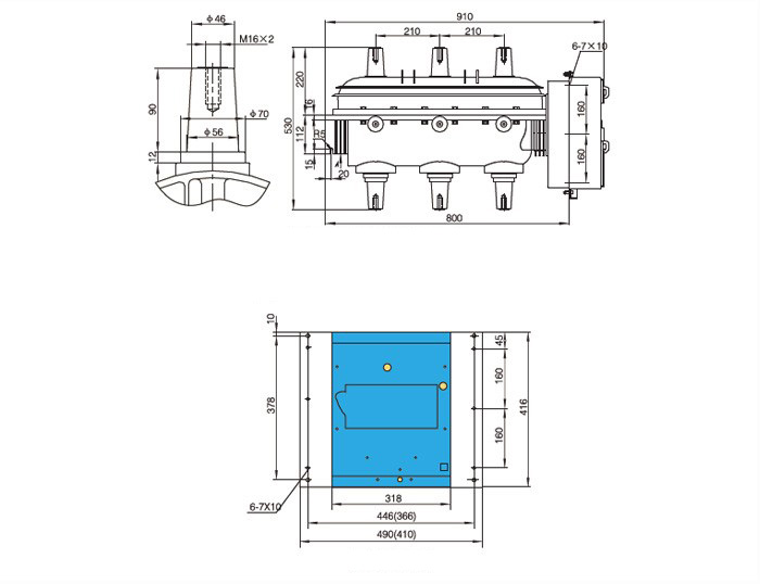
Overall and mounting dimensions(mm)
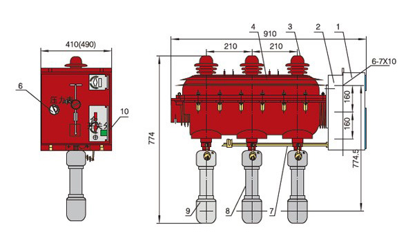
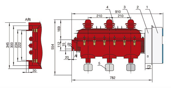
1. mechanism cover
2.mechanism
3.upper terminal shield
4.load switch body
5.lower terminal shield
6.SF6 pressure gauge
7.impact trip mechanism
8.fuse
9.lower fuse contact seat
10.tripping button